As electronic systems become more complex, it’s now more important than ever to utilize accurate and thorough component testing.
Whether you’re assessing components during the manufacturing process, conducting routine maintenance, or performing failure analysis, testing is a vital step to ensure the reliability and optimal performance of electronic systems.
Below, we will cover basic and advanced component testing techniques, explain how to test specific component types and provide some DIY tips. We’ll also explain how AGS Devices can assist in electronic component testing and give you an insight into our certifications and protocols.
Understanding Electronic Components
Understanding electronic components and their functions is essential for anyone interested in electronics, whether for hobby projects, educational purposes or professional work.
The most common components include:
- Resistors: Resistors limit the flow of electrical current in a circuit.
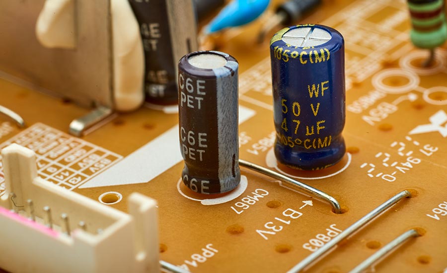
- Capacitors: Capacitors store electrical energy temporarily and can release it when needed.
- Inductors: Inductors store energy in a magnetic field when electric current flows through them.
- Diodes: Diodes allow current to flow in one direction only.
- Transistors: Transistors are used to switch and amplify electronic signals.
- Integrated circuits (ICs): ICs are miniaturized circuits that can perform a variety of functions depending on their design.
- Relays: Relays are electrically operated switches.
- Transformers: Transformers are used to transfer electrical energy between two or more circuits through electromagnetic induction.
- Light emitting diodes (LEDs): LEDs are used as indicator lights in devices and for general lighting.
- Potentiometers and variable resistors: Potentiometers and variable resistors are resistors whose resistance can be adjusted manually.
- Switches and push-buttons: Switches and push-buttons are mechanical devices used to connect or disconnect parts of a circuit.
- Connectors and terminals: Connectors and terminals are used to connect different parts of a circuit, either temporarily or permanently, like USB ports or battery terminals.
Why Testing Electronic Components is Important
Testing electronic components is essential to the quality, reliability, and safety of electronic devices. It helps identify defects and non-compliance with specifications before components are integrated into larger systems, thus preventing potential hazardous and costly failures.
Regular testing also helps maintain the performance of electronic systems over time and is crucial in applications where precision and functionality are critical, such as in medical devices, automotive, and aerospace industries.
Standard Electronic Component Testing Techniques
Standard electronic component testing techniques vary in complexity and depend on the type of component and the specific aspect of its functionality that needs to be verified.
Here’s an overview of each of the listed testing techniques:
1. Visual Inspection
Visual inspection is the simplest form of testing electronic components. It involves carefully examining the component for any physical damage such as cracks, burns, corrosion, or any signs of overheating.
A magnifying tool or a microscope might be used for small or intricate components. This method is especially useful before and after soldering components onto a circuit board, helping to identify issues like cold solder joints or damaged traces.
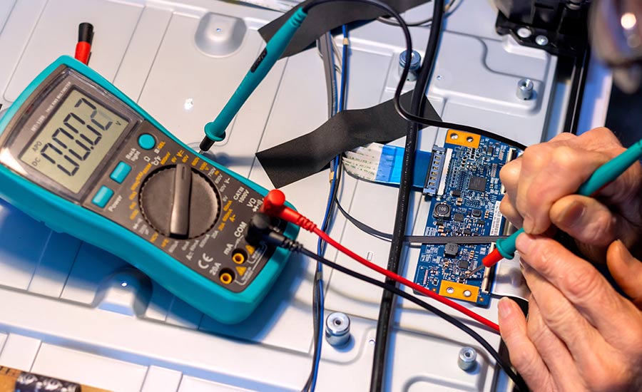
2. Multimeter Testing
Multimeter testing is a fundamental technique used to measure basic electrical properties like voltage, current, and resistance. By using a multimeter, you can quickly diagnose common issues like open circuits, short circuits, or components that do not operate within their specified range.
Checking a resistor’s resistance against its rated value, testing a diode’s forward and reverse bias characteristics, or verifying the voltage across a circuit element are all examples of multimeter testing. This method is applicable to virtually all types of electronic components.
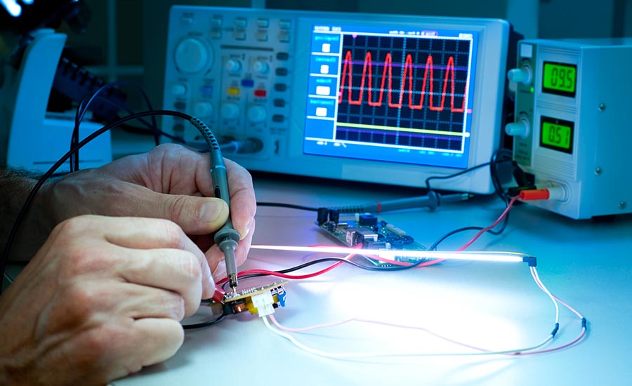
3. Oscilloscope Analysis
Oscilloscope analysis involves using an oscilloscope (or O-scope) to visually display and analyze the waveform of an electronic signal. This technique is crucial for examining the characteristics of electronic signals, such as their amplitude, frequency, shape, and any distortions or noise.
It’s particularly valuable in complex circuits where the timing and shape of signals are critical, such as in digital circuits, communication systems, and power electronics. Oscilloscopes can also be used to troubleshoot issues like signal interference or bandwidth limitations.
4. Continuity Testing
Continuity testing checks if there is a complete path for current to flow in a circuit. It is typically performed using a multimeter set to the continuity mode, which emits an audible beep if continuity is present.
This test ensures that connections are secure and there are no breaks or short circuits. It’s particularly useful for checking solder joints, wire connections, and the integrity of conductive tracks on printed circuit boards.
5. Capacitance and Inductance Testing
Capacitance testing measures the ability of a capacitor to store an electric charge, while inductance testing checks the ability of a coil to stop an electrical current from flowing through it.
Specialized meters, often LCR (Inductance, Capacitance, Resistance) meters, are used for these measurements. This testing is vital in circuits where the timing, filtering, or resonance characteristics depend on these components, such as in power supplies, radio frequency circuits, and oscillators.
6. Frequency Testing
Frequency testing involves measuring the number of cycles completed per second by oscillating signals within a circuit. This can be done using frequency counters or oscilloscopes.
It is essential in applications where the frequency of operation is crucial, such as in communication systems, digital circuits (like microprocessors and clock circuits), and in systems where signals are modulated or demodulated.
7. Signal Generator Usage
Using a signal generator involves creating controlled and predictable electronic signals to test the response of a circuit. Signal generators can produce various waveforms (like sine waves, square waves, pulses) at a range of frequencies.
This method is particularly useful in testing and calibrating electronic equipment, analyzing the frequency response of circuits, and simulating conditions that a circuit might encounter during normal operation.
how components were tested by providing more accurate and precise readings
Advanced Electronic Component Techniques
Advanced testing techniques are important in the modern electronics industry to ensure reliability and performance of components in increasingly complex systems all over the world.
The most common advanced testing techniques include:
1. Automated Test Equipment (ATE)
Automated Test Equipment (ATE) is used for testing electronic components and systems in a fast, efficient, and highly repeatable manner. ATE setups usually consist of computer-controlled equipment that automatically conducts tests and records results, making it ideal for high-volume manufacturing.
ATE can perform a wide range of tests, from basic parameter measurements to complex functional verifications, significantly reducing testing time and human error.
2. In-Circuit Testing (ICT)
In-Circuit Testing (ICT) involves testing the components on a printed circuit board (PCB) individually while they are part of the circuit. This method uses a bed-of-nails tester — a series of spring-loaded pogo pins that come into contact with the test points on the PCB.
ICT can detect problems like shorts, opens, incorrect component values, and wrong component orientations. It is highly effective for ensuring manufacturing accuracy but requires a custom fixture for each PCB design.
3. Functional Testing
Functional testing verifies that each function of the electronic hardware is operating in accordance with its specification. This test simulates the operational environment of the hardware and checks for the correct output in response to specified inputs.
Functional tests can range from simple tasks, like turning on a device, to complex software-driven tests that simulate full operational conditions. This approach is crucial for final product verification.
4. Environmental Stress Testing
Environmental stress testing subjects electronic components or systems to extreme environmental conditions to ensure their reliability and durability.
This can include temperature cycling, humidity testing, vibration testing, and shock testing. These tests are crucial for assessing how components will perform under harsh environmental conditions, such as in automotive, aerospace, or outdoor applications.
5. X-Ray Inspection
X-Ray inspection is used to examine the internal structure of electronic components and solder joints in a non-destructive way. This technique is particularly useful for identifying manufacturing defects like solder bridges, voids, and misalignments in PCBs, especially for surface mount devices and ball grid arrays (BGAs) where visual inspection is not feasible.
X-Ray inspection provides a detailed view of internal structures, ensuring the integrity and quality of soldering and internal component structures.
6. Time Domain Reflectometry (TDR)
Time Domain Reflectometry (TDR) is a method used to test the integrity of cables and connectors. By sending a signal down a cable and measuring the reflections that return, TDR can pinpoint the location and nature of cable faults such as breaks, shorts, or poor connections.
It is essential for diagnosing problems in complex wiring systems and high-frequency signal paths, like those found in telecommunications and high-speed data applications.
7. Network Analysis
Network analysis involves measuring the network parameters of electrical networks, such as amplifiers and filters. Using a network analyzer, this technique measures properties such as signal gain, loss, phase shift, and reflection at various frequencies.
This test is important for characterizing and tuning radio frequency (RF) and microwave systems, ensuring that components like antennas, filters, and transceivers meet their specified performance criteria.
How To Test Various Types of Electronic Component
Testing various types of electronic components requires specific methods and tools to accurately assess their functionality and detect potential issues.
Here’s a brief overview of how to test different component types:
1. How To Test Resistors
Testing resistors typically involves measuring their resistance value using a multimeter.
To test a resistor, you should:
- Turn off power: Ensure the circuit is not powered.
- Remove the resistor: If possible, remove the resistor from the circuit for accuracy.
- Set multimeter: Switch the multimeter to the resistance (Ω) measurement mode.
- Connect probes: Attach the multimeter probes to the resistor’s leads.
- Read value: Observe the resistance value on the multimeter.
- Compare values: Check if the measured value matches the resistor’s stated value.
- Inspect for damage: Visually check the resistor for signs of physical damage.
2. How To Test Capacitors
Capacitors can be tested using a multimeter with a capacitance measurement function.
To test capacitors, you should:
- Discharge the capacitor: Safely discharge the capacitor to prevent any potential electric shock or damage.
- Remove from circuit: Ideally, remove the capacitor from the circuit for accurate testing.
- Set multimeter: Turn your multimeter to the capacitance measurement mode.
- Connect probes: Attach the multimeter probes to the capacitor’s terminals.
- Read value: Check the capacitance value displayed on the multimeter.
- Compare values: Match this reading with the capacitor’s rated capacitance value.
- Inspect for physical damage: Look for signs of bulging, leakage, or other damage.
3. How To Test Switches and Connectors
Testing Switches:
- Set multimeter to continuity mode: Adjust the multimeter to the continuity test setting.
- Test in open position: With the switch in the off position, place the multimeter probes on the switch terminals. The multimeter should not show continuity (high resistance or open circuit).
- Test in closed position: Turn the switch to the on position and check again with the probes. The multimeter should indicate continuity (low resistance).
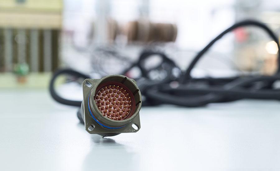
Testing Connectors:
- Set multimeter to continuity mode: Switch your multimeter to the continuity setting.
- Test each pin: Place one probe on a pin and the other probe on the corresponding connecting point (like the other end of the cable or the matching pin of a mating connector).
- Check for continuity: The multimeter should indicate continuity for each connected pin pair.
- Test for short circuits: Also check between adjacent pins to ensure there’s no continuity, indicating a short circuit.
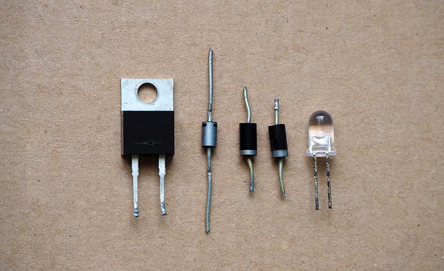
4. Diagnosing Issues with Semiconductors
Semiconductors, like diodes and transistors, can be tested using a multimeter diode function.
For diodes, the meter should show low resistance in one direction (forward bias) and high resistance in the opposite direction (reverse bias).
For transistors, testing involves checking the junctions between the base, collector, and emitter for similar forward and reverse bias behaviors. More complex semiconductors may require specialized test equipment and procedures.
Semiconductor production testing is a critical phase in chip production.
DIY Testing Tips and Tricks
If you’re a do-it-yourself enthusiast or involved in hands-on electronics work, having practical testing tips and tricks up your sleeve can be helpful.
Here are some useful DIY testing tips for electronic components:
- Understand component functionality: Before testing, make sure you understand what the component is supposed to do in the circuit. This will help you understand which tests to perform and what results to expect.
- Organize your workspace: A clean and organized workspace helps prevent loss or damage to components and makes testing more efficient. Use compartments or trays to keep small components from getting lost.
- Use the right tools: Invest in a good quality multimeter, soldering iron, and other essential tools. A well-equipped toolbox is crucial for effective testing and troubleshooting.
- Follow safety protocols: Always disconnect the power before testing and be aware of the risks involved, especially with high voltage or power circuits.
- Start with visual inspection: Careful visual inspections can help you identify many potential issues. Look for signs of damage, overheating, loose connections, or corroded contacts.
- Compare components in good condition: To ensure a component is functioning properly, compare it with a new one or another of the same type which is known to be in good working condition.
- Learn to read schematics: It’s essential to know how to read and understand schematic diagrams. It will help you identify components and their connections within the circuit.
- Test components in a controlled environment: Whenever possible, remove the component from the circuit for isolated testing. This ensures more accurate results.
AGS Devices: A Reliable Partner for Testing Electronic Components
AGS Devices implements a robust quality control system that includes incoming receiving inspection, quality authenticity testing, and outbound shipment verification to ensure the quality and authenticity of our products before they are shipped to customers.
We provide rigorously tested electronic components to ensure quality and reliability when partnering with clients.
Our testing process includes:
- Mechanical Testing
- Acid Decapsulation
- Digital Microscopy
- X-Ray Analysis
- LCR Testing
- Solderability
Besides distributing electronic components, we also offer services such as:
- Sourcing and Procurement
- BOM Management
- Shortage & Obsolescence Solutions
- Excess Material Acquisition
As a leading distributor of electronic components, our goal is to boost the efficiency and reliability of your supply chain. Our knowledgeable team uses the latest technology and industry insights to provide top-tier testing solutions at competitive prices.
AGS Devices Certifications and Protocols
At AGS Devices, we take pride in adhering to globally recognized standards and maintaining the highest level of quality in our products and services.
Our commitment to quality is underscored by our certifications to renowned standards, including:
- ISO 9001:2015 – Quality Management System
- AS 9120:2016 Rev B – Quality Management System for Aviation, Space, and Defense Distributors
- ISO 14001 – Environmental Management System
- IDEA-STD-1010-B – Acceptability of Electronic Components Distributed in the Open Market
- IPC-A-610D – Acceptability of Electronic Assemblies
- ERAI – Electronic Resellers Association International
- ITAR – International Traffic in Arms Regulation
FAQs About Electronic Component Testing
If you didn’t find the answers you needed in this post here is some additional information you might need when testing electronic components.
How do you check electronic components?
To check electronic components, you typically use a multimeter or other specialized electronic testing equipment.
The process of checking electronic components includes:
- Identify the component: Recognize the type of component you are testing (resistor, capacitor, diode, etc.).
- Understand its function: Know what the component is supposed to do and its standard values or behaviors.
- Disconnect power: Ensure the component is not live.
- Use the appropriate tools: Use a multimeter for basic tests like continuity, resistance, capacitance, etc. More complex components might require oscilloscopes or specialized testers.
- Conduct tests: Perform tests relevant to the component (e.g., resistance test for resistors, capacitance test for capacitors).
- Compare with standard values: Compare the test results with the expected values to determine if the component is functioning correctly.
How do you test components in a circuit?
To safely test components in a circuit, do the following:
- Power off the circuit: Ensure the circuit is not energized.
- Identify test points: Determine where to place test probes for minimal disturbance to the circuit.
- Use a multimeter/oscilloscope: Connect the test equipment without removing the component from the circuit, if possible.
- Conduct functional tests: Perform tests like voltage and current measurements across the component, continuity tests, or signal tracing.
- Interpret results: Analyze the results in the context of the circuit’s operation to assess component functionality.
How do you troubleshoot electronic components?
To troubleshoot electronic components, begin by identifying the symptoms of the malfunction. Conduct a visual inspection for any obvious damage and use a multimeter to test individual components for continuity, resistance, voltage, and other relevant parameters.
How do you find a faulty component in a circuit?
To find a faulty component in a circuit, start with a symptom analysis and a thorough visual check for signs of damage or overheating. To identify the problem, test each component in the circuit you suspect is not working properly.. Tools like a multimeter are essential for checking continuity, voltage, and resistance.