If you’re working in the electrical or electronics field, understanding electrical symbols is mandatory knowledge.
Experts who use electrical symbols can reduce design errors by up to 40%, saving time and money in residential and industrial projects.
We’ll break down essential electrical symbols from basic to advanced, so you can confidently navigate electrical schematics and enhance your technical skills.
What Are Electrical Symbols and Why Are They Important?
Electrical symbols are simple drawings representing different parts of electrical circuits, like wires, switches, or batteries.
Instead of using lengthy descriptions, electrical symbols instantly show how circuits work, supporting electrical system design, repair, or analysis.
Electrical symbols are important because they offer a universal language for engineers, electricians, or technicians working on a certain project. If you’re a professional using these symbols, it also simplifies specifying components during repairs or maintenance.
Basic Electrical Symbols
Understanding basic electrical symbols is the first step to reading and interpreting electrical schematics.
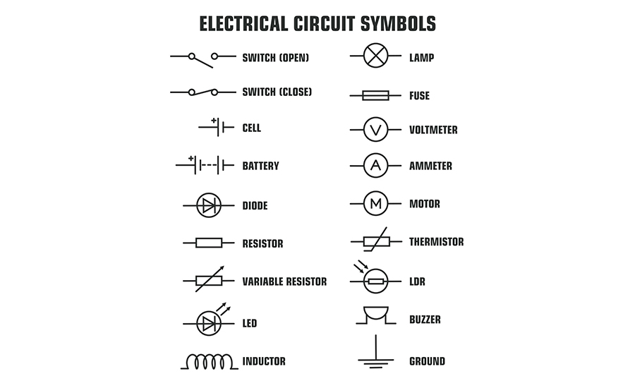
Basic electrical symbols include:
Resistors, Capacitors, and Inductors
- Resistor symbol: The symbol for resistors is typically a zigzag line or a rectangle, depending on the schematic standard you’re following. This symbol helps identify where the circuit controls the flow of current to manage voltage levels and protect components.
- Capacitor symbol: The capacitor symbol features two parallel lines, with one variation incorporating a curved line to represent polarized capacitors, which indicates positive and negative terminals. This symbol signifies the placement of capacitors within a circuit.
- Inductor symbols: The inductor symbol is a series of loops or coils and indicates stored energy in a magnetic field. Recognizing inductor symbols helps filter signals, tune circuits, and manage high-frequency noise.
Power Sources: Batteries and Power Supplies
- Battery symbol: This symbol consists of a series of alternating long and short lines. Each set represents a cell, with the long line indicating the positive terminal. Battery symbols show where power is stored and how it flows through the circuit, helping you identify which components rely on this stored energy for operation.
- Power supply symbol: Power supply symbols are typically represented by a circle with lines indicating positive (+) and negative (-) outputs. Recognizing power supply symbols helps identify how power flows through a circuit and which components rely on it.
Switches and Relays
- Switch symbol: Switch symbols indicate circuit points where you can control the current’s flow. Common types include the Single Pole Single Throw (SPST) and Single Pole Double Throw (SPDT) switches. An SPST switch appears as a simple line break, while an SPDT includes additional connections for toggling between two states.
- Relay symbol: Relay symbols often include a coil, representing the relay’s electromagnetic mechanism, along with a set of switch contacts. Recognizing relay symbols helps identify where a relay is used to switch a circuit on or off in response to an electrical signal. This low-power signal activates the relay, which then controls high-power devices by switching circuits, allowing for safe and efficient control of larger systems with minimal input.
Intermediate Electrical Symbols
Intermediate electrical symbols go beyond the basics, representing more complex components like diodes, transistors, and integrated circuits.
Intermediate electrical symbols include:
Diodes, Transistors, and Integrated Circuits (ICs)
- Diode symbol: The diode symbol is a triangle pointing to a line. The triangle represents the direction of current flow in the circuit, allowing engineers to manage and prevent reverse current.
- Transistors symbol: Transistors, the building blocks of digital circuits, are represented by a variety of symbols depending on the type. Transistor symbols show how current flows through different parts (emitter, base, and collector for BJTs or the source, gate, and drain for FETs), enabling the amplification or switching of signals in digital and analog circuits.
- Integrated circuit symbol (ICs): IC symbols are usually rectangles with multiple input and output pins on the sides. IC symbols help identify where multiple functions, like amplification, timing, or processing, are performed within a circuit.
Transformers and Motors
- Transformer symbol: The transformer symbol features two coils with lines or dots between them, representing their magnetic coupling. These symbols are essential for raising or lowering voltage levels in power distribution systems.
- Motor symbol: Motor symbols typically feature a circle with an ‘M’ inside, sometimes accompanied by additional elements that indicate specific motor types (e.g., DC or AC motors). Recognizing these symbols is useful when working with devices that involve motion control, such as fans, pumps, or robotic arms.
Advanced Electrical Symbols
Advanced electrical symbols represent components in complex circuits and systems, especially in communication, computing, and high-frequency applications.
Advanced electrical symbols include:
Communication Systems and Antennas
- Antenna symbol: The antenna symbol often looks like a line with a series of waves coming from the top, representing its ability to transmit and receive electromagnetic signals. The antenna symbol shows where wireless communication occurs in systems like radios, Wi-Fi routers, and cell phones.
- Communication module symbol: Symbols for communication modules, such as RF (Radio Frequency) transmitters or receivers, vary but typically include lines or boxes with labels for specific function. They highlight component locations in a circuit that handles data transmission and reception.
Grounding and Shielding
- Ground symbols: The most common types are earth ground (a set of descending lines) and chassis ground (a vertical line with multiple horizontal lines below). Ground symbols indicate the circuit’s voltage reference point and where excess current is safely directed for damage prevention.
- Shielding symbol: Shielding symbols usually appear as a dotted or dashed line around a component or section of the circuit. Recognizing shielding symbols is crucial for identifying components shielded from external noise in high frequency or sensitive circuits.
Microcontrollers and Microprocessors
- Microcontroller symbol: Rectangular with multiple pins on each side, the microcontroller symbol indicates core processing in a circuit that controls tasks like data handling, communication, and sensor management.
- Microprocessor symbol: Microprocessors have a rectangular symbol with labeled pins but often have more complex input/output configurations. The microprocessor symbol indicates the presence of an advanced processing unit for complex computing tasks found in computers, smartphones, and embedded systems.
Best Practices for Using Electrical Symbols
To make electrical designs clear and easy to understand, follow these best practices:
Standardization and Compliance
- Be consistent with symbol usage across your schematics.
- Follow established standards like IEC or ANSI to ensure all users can easily read your diagrams.
- Standardized symbols also help meet regulatory requirements, which is especially important in industries like automotive and medical devices.
- Aligning with these standards reduces errors and helps pass inspections more easily.
Custom Symbols
- Use custom symbols for unique or multi-functional components or when necessary.
- Avoid confusion by keeping custom symbols simple and labeling them clearly with a legend.
- Overusing custom symbols can complicate diagrams, so use them sparingly and only when standard symbols don’t suffice.
Learn More About Electrical Symbols With AGS Devices
At AGS Devices, we understand how important it is to accurately interpret electrical symbols for clear design and troubleshooting in your projects.
With our broad industry expertise, we support engineers and technicians by providing high-quality components, making it easier for you to connect the right parts and symbols in your schematics.
Whether you’re working on basic circuits or advanced systems, AGS Devices is here to support your goals with accurate, up-to-date information and fast delivery of essential components.
Besides providing basic electrical knowledge support, we also provide services such as:
- Sourcing and Procurement
- BOM Management
- Shortage and Obsolescence Solutions
- Excess Material Acquisition
Our dedicated account representatives work closely with you to ensure you’re always equipped with the right parts and solutions for your electrical projects. We keep communication open, making sure you’re the first to know about any updates that could impact your workflow.
Start improving your electrical designs with AGS Devices today.